Catalog of Electrical Components As Used By Gibson in the 1950s and 1960s
This page may not be linked to and posted on other sites without written permission from Rick Norman
Images on this page may not be used outside of this page without written permission from Rick Norman
Click here to visit my Grover Tuner Reference Page
This page shows some of the various interesting things about the major pieces and wiring execution of the Gibson wiring harnesses of the 1950s and into the 1960s.
For many years I have been renewing and reconditioning these great old vintage wiring harnesses. I've done this for well-known vintage parts dealers, individual owners, and for my own instruments. Doing this work has seen hundreds of old Centralab and IRC pots, Grey Tiger and Sprague caps, and Switchcraft switches galore pass through my hands. I've also repaired a ton of vintage Gibson (and Fender, to be truthful) pickups, but those pictures and tales will be the subject of another page.
I have also had my hands, tools (and camera lens) inside more old Gibson electric guitars than I could possibly count - definitely considerably more than I could have predicted when I first started doing this simply for my own instruments. I've had the good fortune of seeing enough to have a good eye for when something is different or unusual, or... wrong. I've attempted to capture some of the interesting variances of these parts and wiring.
This page is a living document. I will be adding pictures and information as I learn it. Check back often!
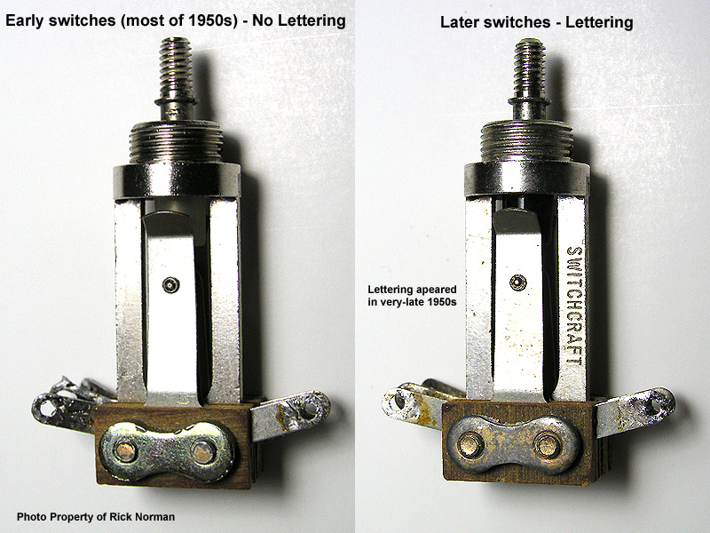
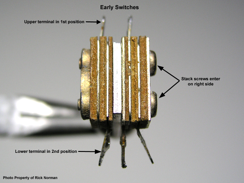
Switchcraft 3-way Toggle Switches
The switches used through most of the 1950s had no lettering on them that identified them as Switchcraft brand switches. That changed in the very-late 1950s (as best I can tell), if not into 1960.
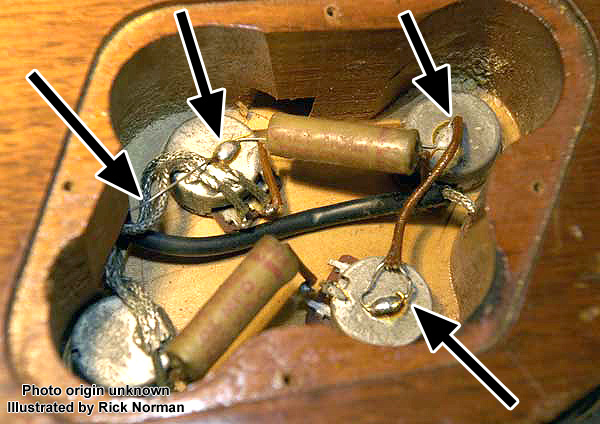
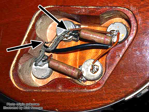
The simple way was to join the two upper terminals together and connect the lead to the output jack to that junction. That method did get used back as far as the earliest Les Pauls (I've handled an 'orange wire' '52 harness that was wired that way), and appeared throughout the 1950s. But despite its simplicity, it wasn't the only method found in the 1950s.
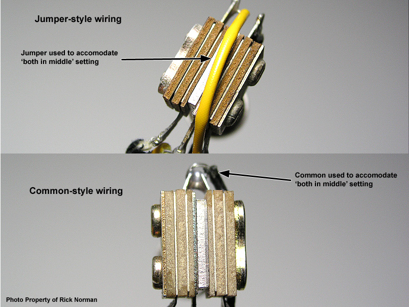
The more complicated method was to run the pickup leads to different terminals than you see in the 'simple method' and then run an extra piece of wire across the back of the switch in the form of a jumper to accomplish the 'both pickups on' function in the middle switch position. This was used at least as often in the 1950s as the 'simple' method.
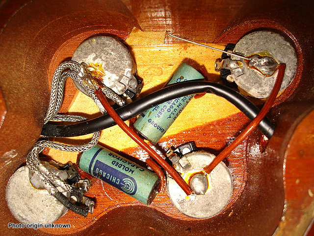
Why were two different methods used? There's no way to know for sure. I personally believe that the wiring method varied with whomever was assigned to the soldering station at the Gibson plant on any given day. Just my opinion, of course. Here's a picture showing both ways:
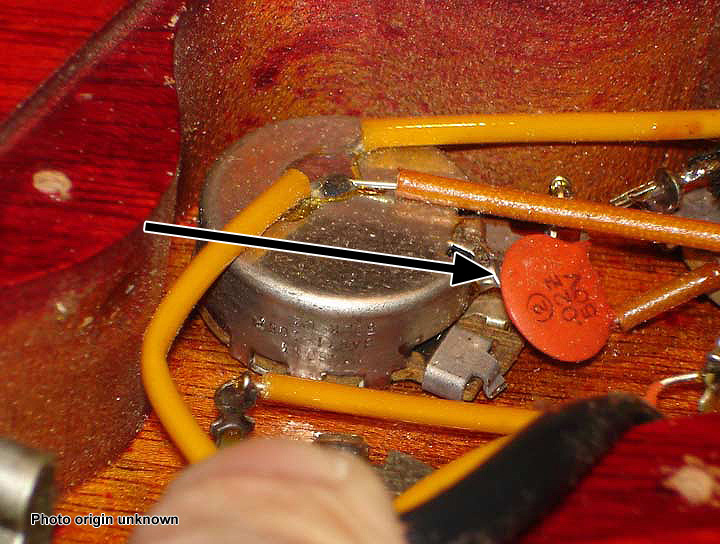
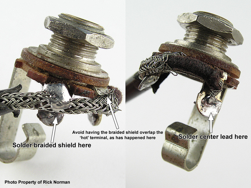
The pickup(s) grounds to its respective volume control through the braided shield on its lead.
Then, the volume controls ground through the braid shield on each lead going to the selector switch, which, through the connection shown in the picture below, grounds to the final lead running to the output jack, completing the ground plane for the entire guitar.
All that leaves is grounding the tone control pots. In a Les Paul, the nearest connection to the ground plane is through one or both volume pots.
Various schemes were used to connect the tone control to its mating volume control. But that's not the point of this picture...
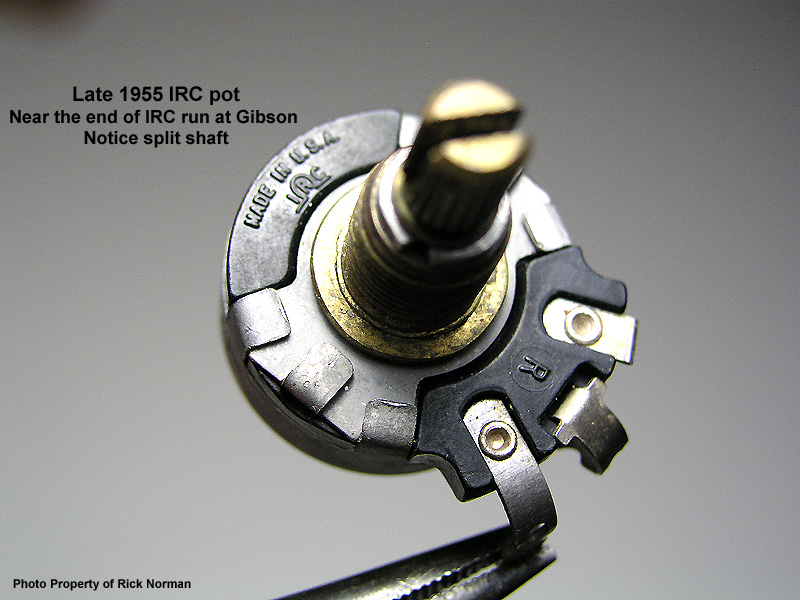
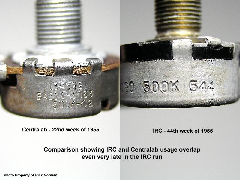
IRC Pots
The latest IRC pots I've seen in Gibson use was up to very-late 1955. In a couple of cases, I've had a wiring harness that used both brands simultaneously. For example, I once had a completely-original very-early 1956 Les Paul Junior harness that had a very-late 1955 IRC volume pot and a very-early 1956 Centralab tone pot, with a Grey Tiger tone cap. (If anyone has evidence of later IRC pots, please forward that information to me!)
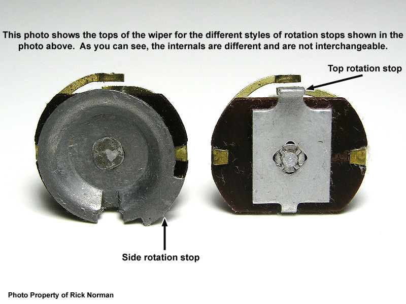
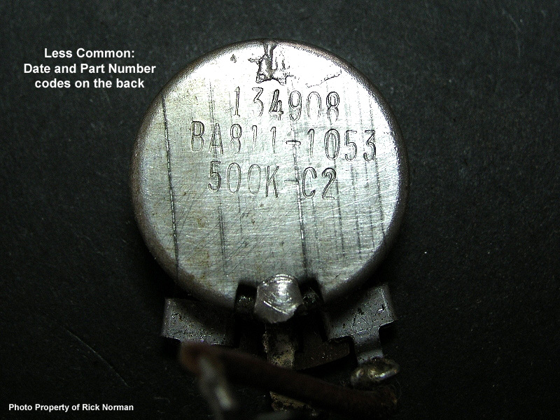
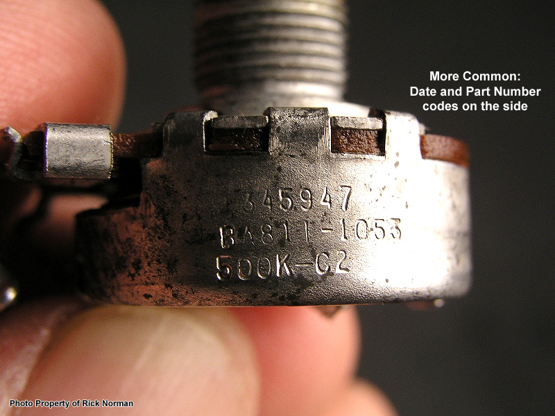
IRC pots changed little during their use in the 1950s. The major notable changes were to migrate from a solid shaft to a split shaft (as did the Centralabs), and a slight change to some of the coding stamped into the back cover. The following pictures will show some of the variations.
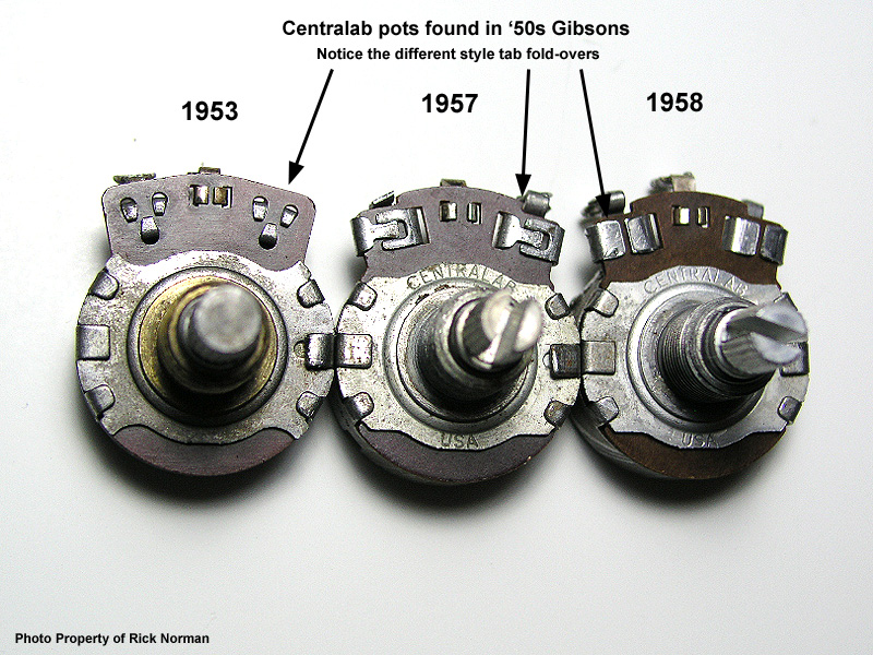
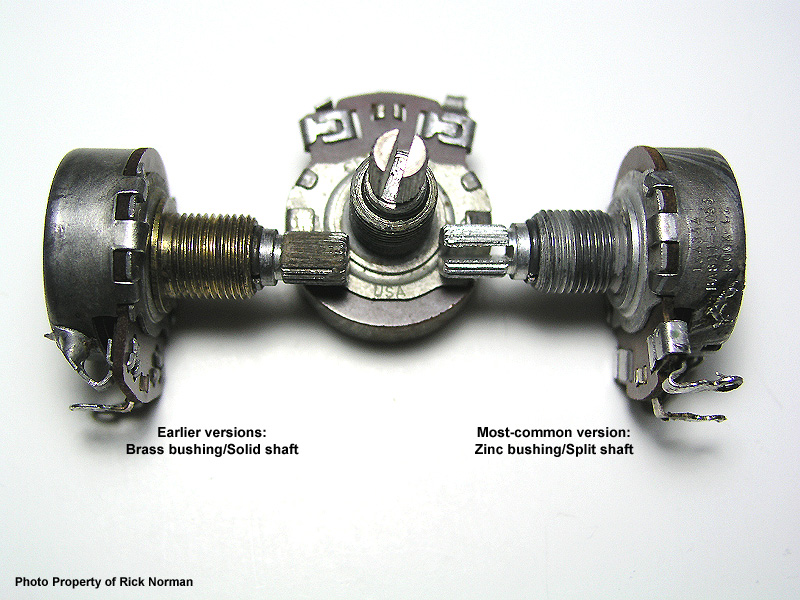
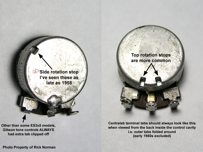
Centralab Pots
As with many of the hard-parts that Gibson used in the '50s, features of the Centralab pots changed over the years. The following pictures will show some of the variations.
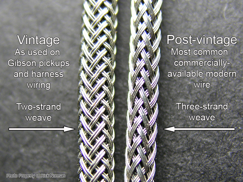
Braided-shield Connecting Wire - Vintage v. Modern
This happens to be one the few things in the Gibson guitar electrical chain that literally makes no difference in tone (along with the selector switch and the output jack). I believe the change occurred outside of Gibson's hands, meaning perhaps their wire vendor changed its manufacturing practice and that was that. Or they just changed vendors outright, possibly because they got a better deal from someone else. Since it literally makes no difference, there was no reason not to go with the best price. We could guess all day, couldn't we?
Tone Capacitors Over The Years
'Chicago' Capacitors
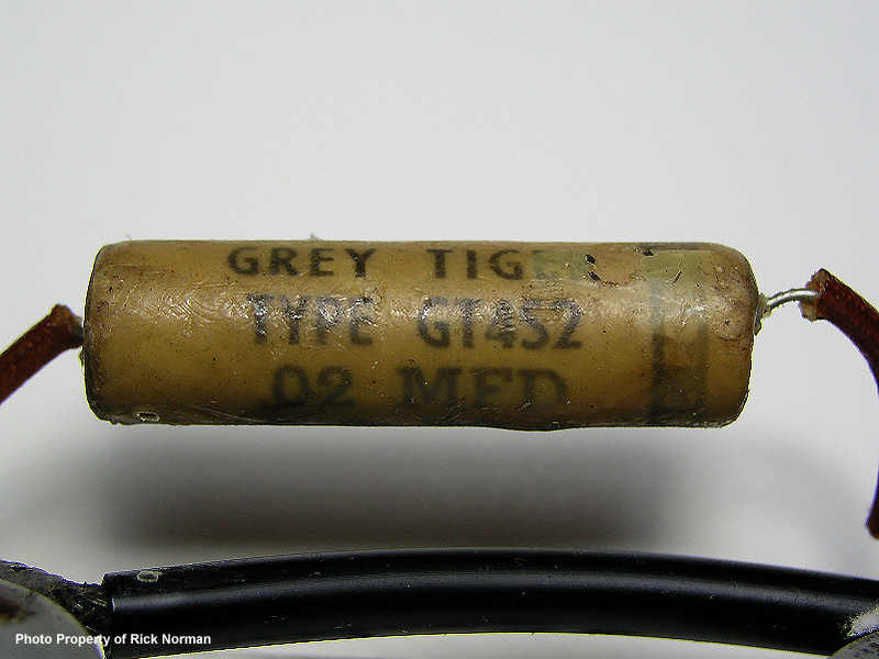
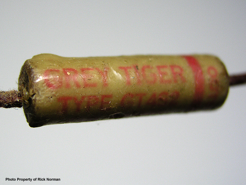
'Grey Tiger' Capacitors
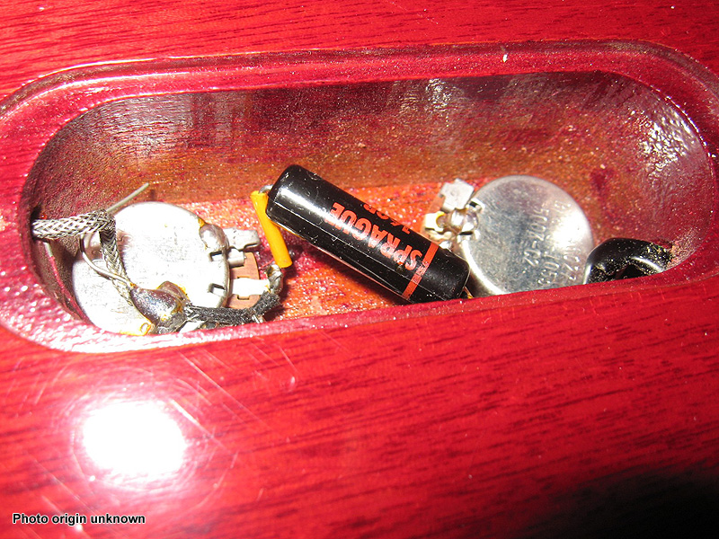
'Sprague Black Beauty' Capacitors
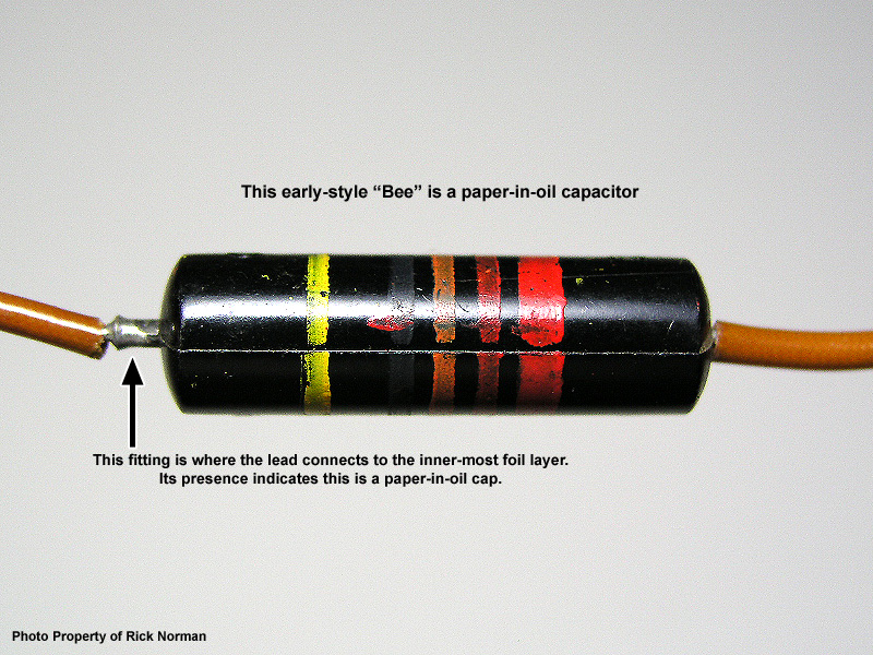
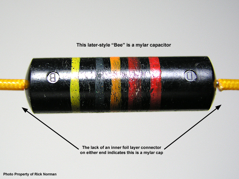
The first version of the Black Beauty model to be used by Gibson was of 'paper-in-oil' (PIO) construction, which was very common across many other capacitor manufacturers in those days. Look at the picture below. It shows how to identify a PIO version of the Black Beauty.
Using Old PIO 'Bees' in Modern Guitars
More directly, it's 'iffy' whether an old 'Bee' is still actually the value that its labeling says it is. Over the course of my years of reconditioning old Gibson harnesses, using a good quality dedicated capacitance meter, I've measured every single capacitor in every single harness sent my way, not even counting the loose 'Bees' sent my way. I can say with absolute authority that a full 30% of them have drifted upward in value. I've had .022uf PIO 'Bees' measure as high as .035uf.
I'm not saying you shouldn't use old PIO 'Bees' in a modern guitar, or in your vintage restoration, etc. I'm suggesting that you hunt down caps that have been tested. I personally would be very wary of any old PIO cap that was known to have come out of an old TV set, hi-fi set, public address amplifier, etc. - anything that operated at high voltage. I just don't advocate having old PIO 'Bees' in any modern guitar just for the sake of it... when there's a measurable chance that it will actually hurt your tone. I'm suggesting that, for modern guitars, it's better to have modern, in-spec capacitors in your guitar than old-but-out-of-spec 'Bees' just for the sake of bragging rights. I'm also suggesting that if you're restoring an old Gibson that would originally have had 'Bees', keep searching for a pair that can be proved to still be of the rated value.
I'll get off my soap box now... LOL
Second Version of the Black Beauty
Final Version of the Black Beauty
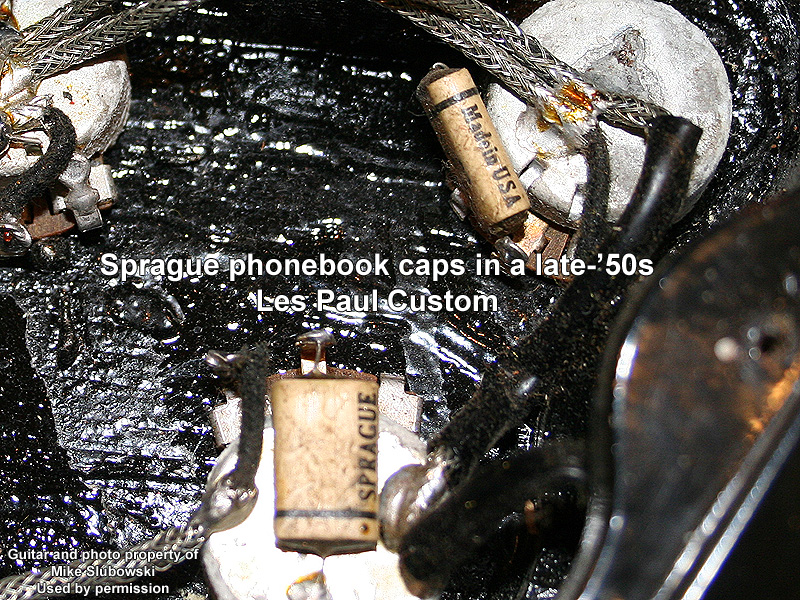
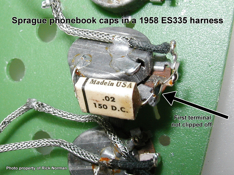
'Sprague Phonebook' Capacitors
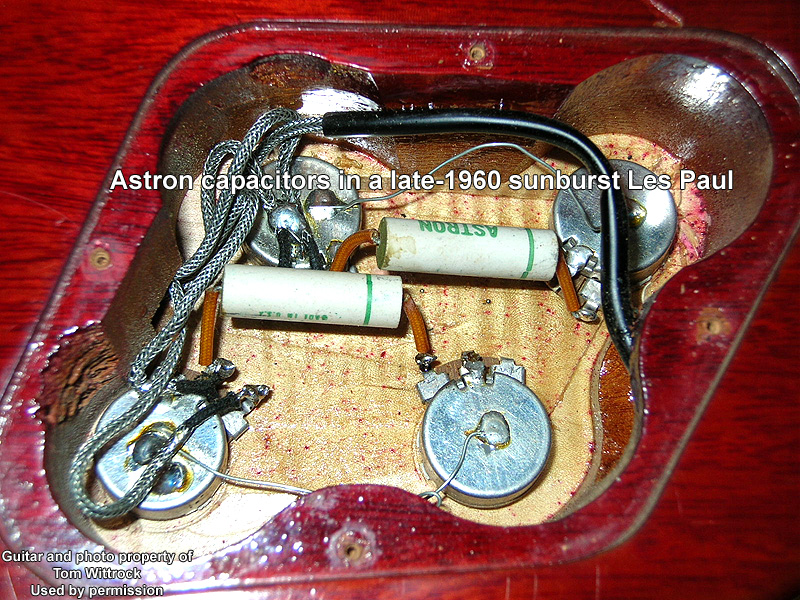
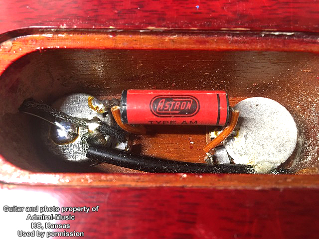
'Astron' Capacitors
And finally...
Ground Those Tone Pots!
What I will say is that instruments like ES models and Juniors kept it simple. A Junior, for example, simply soldered the braided shield of the output lead going to the output jack directly to the casing of the tone pot as the lead was passing by. Similarly, the routing of the leads to the volume and tone pots in ES guitars was such that they also used the braided shield of nearby leads to complete the grounding of the tone pots.
Les Pauls and Les Paul Specials and SGs and such had to make do with different schemes.
Early 50s Les Pauls
Look at the two pictures below - the upper picture is the early-early '52 seen in pictures in other sections. The lower picture is of a '54. Clearly, the order in which the pots are grounded is not important. Also note that in the early days, the ground buss wires had insulation sleeving installed. This didn't go on forever.
Middle-50s (and later) Les Pauls
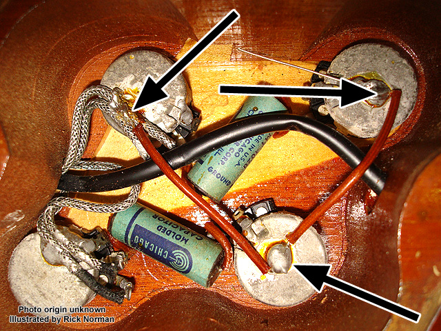
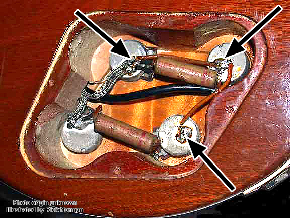
There were two basic configurations. What they had in common is that they got the bridge pickup volume pot into the game. Now the bridge pickup volume and tone pots got connected, and similar for the neck pickup controls.
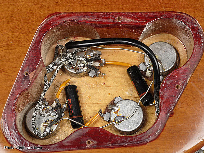
The variation is that sometimes one piece of buss wire got wrapped around to connect all four pots. I call this scheme a 'horseshoe ground'. In the pictures below you see the most common layouts we've all seen before.
Other things to note about the ground buss of this era are that the ground buss is no longer insulated. Also the gauge of the ground buss wire was not consistent. Take a look at the pictures of the '52/'53-era controls - underneath the insulation sleeving is smaller buss wire than what came later. Take a look at the picture of the 'Astron' capacitors in the section on capacitors - the gauge of the ground buss wire is smaller. I've seen this subject (gauge of ground buss wire) debated and fretted over... IT MAKES NO DIFFERENCE. It's the GROUND PLANE, my friends. LOL. It does not effect tone. It does not impact shielding. There was not just one special gauge of wire used. Nuff said. LOL
The first picture shows a very-early wrap-tail guitar. Notice the unused trapeze string ground channel as Gibson was using up the existing stock of trapeze-era mahogany body backs.
This second picture looks to be a late-'55 or early-'56 Goldtop.
String Ground Methods Over The Years
'Trapeze-era' String Grounds
Fairly easy to do on a hollowbody, yes? How did Gibson do it on its first solidbody? Look at the pictures below. In addition the various channels routed into the mahogany body back for the selector switch and pickup leads, a channel was also routed that went between control cavity and the butt of the guitar.
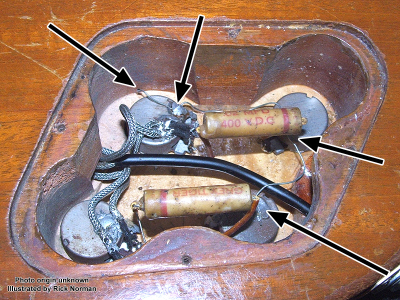
'Wrap-tail-era' String Grounds
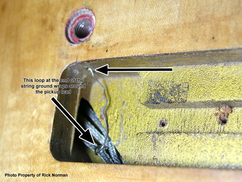
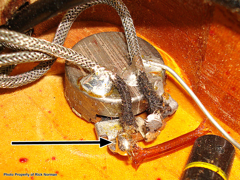
The new method was to drill a hole between the pickup cavity route and the nearest tail piece stud hole. A thin wire was run through the drilled hole from the pickup cavity into the empty High-E stud bushing hole, and then the stud bushing was pressed in. The other end of the wire was then soldered to the nearest available location in the overall ground plane.
Two different methods were used to connect to the ground plane. One, as shown below, was to simply wrap the string ground wire around the braided shield of the pickup lead and solder.
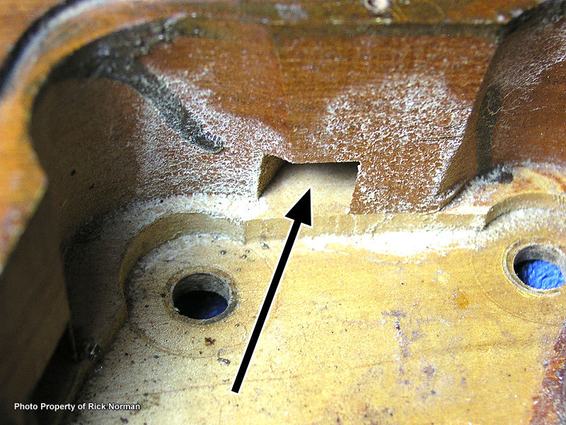
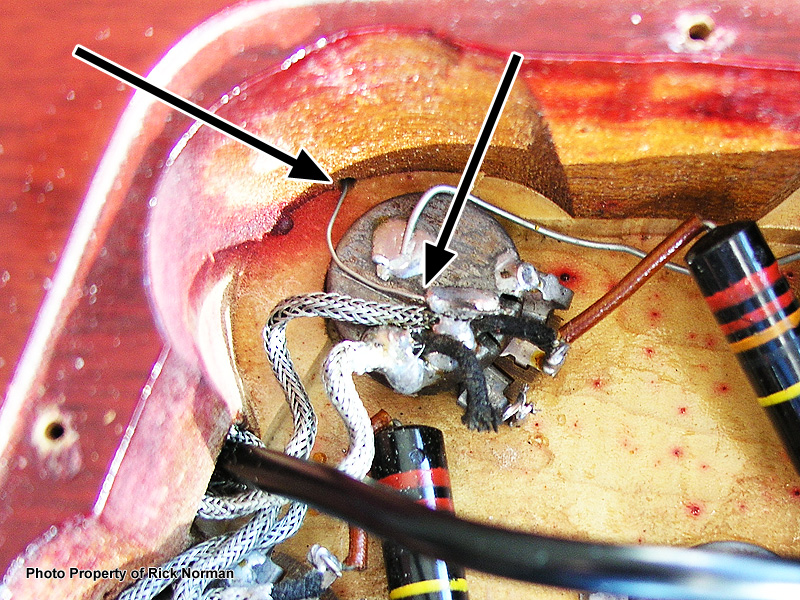
Just for the sake of visuals, here's a picture of a 1957 Les Paul Junior pickup cavity. What there is to see here is a demonstration that one-piece guitar bodies (Les Paul Juniors, Les Paul Specials, and the original 1950s Les Paul Customs) couldn't take advantage of a routed channel for all the leads. For these guitars, all access to the control cavity was via drilled holes.
On a Junior, with only one lead needing to pass between the pickup cavity and the control cavity, the drilled hole was quite small, yet Gibson still ran the string ground down through the tiny hole and soldered it to the volume pot (at least on this particular guitar). Due to the shallowness of the pickup cavity perhaps the assembly person felt there simply isn't enough room to leave a string ground with enough length to comfortably wrap around the pickup lead.
Likewise, I've only seen the insides of a few Les Paul Specials of that era so I'd like to get some good, detailed pictures of the guts of both single-cut and double-cut Les Paul Specials.
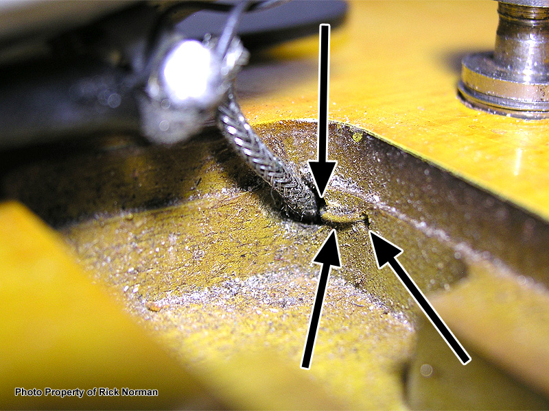
'ABR-era' String Grounds
The displacement of the tail piece placed it in excellent proximity to the control cavity. It was now possible to drill a hole from the High-E-side tail piece stud bushing hole directly into the control cavity, emerging right next to the neck pickup volume control pot. This is the look most of us are most familiar with.
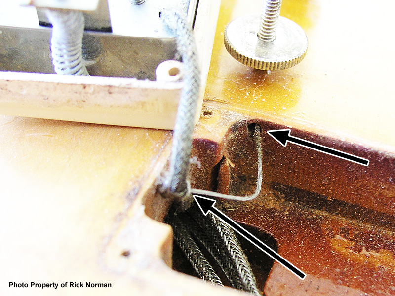
'ABR with Tremolo' String Grounds
Is a new solution required? No, an old one! Meaning, drilling a hole from the bridge pickup cavity to the High-E ABR stud hole, similar to the wrap-tail guitars
This picture shows a 1958 Les Paul, and on this particular guitar, the assembler soldered the free end of the string ground around the bridge pickup lead as shown. Like wrap-tail guitars, the string ground could just as easily been run down the wire channel and soldered to the back of one of the pots.
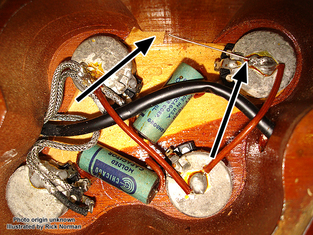
The 'Modern Wiring' Ain't Really So Modern...
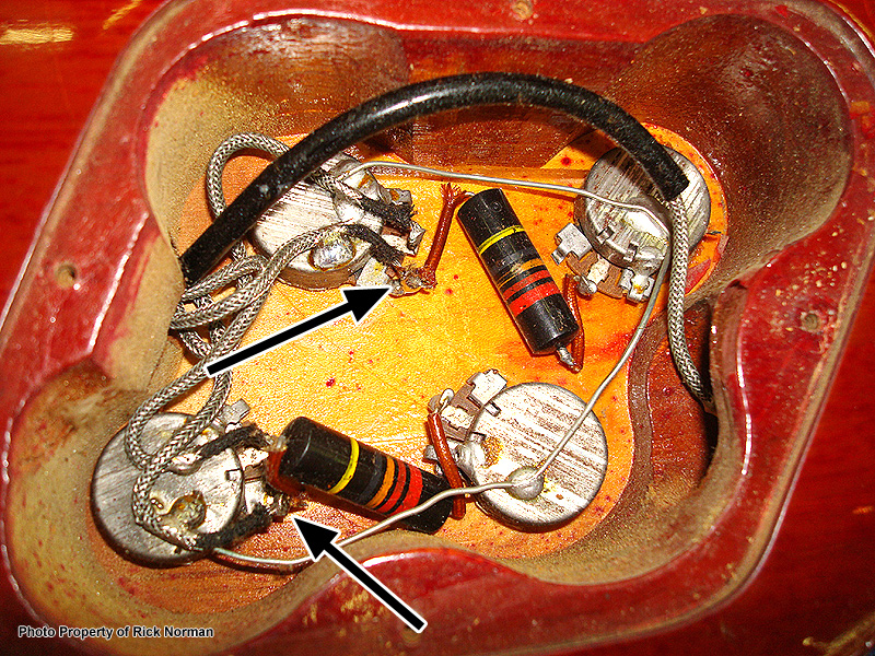
I'm only going to show pictures of one guitar's guts, but believe me, it's 100% factory-original, and it's not a one-off. I've seen this configuration in multiple complete Gibson guitars of the late 1950s, and more examples among the 1950s Gibson harnesses I've received out of the guitar to refurbish.
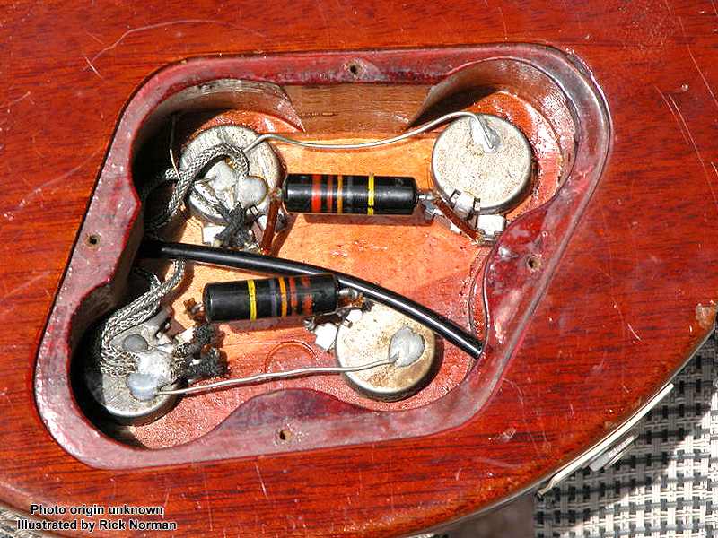
The pictures below are of a 1958 Les Paul that spent some quality time at my house. Its controls are entirely original.
Oh, by the way, also notice that the capacitor lead connected to the tone pot is connected to the center terminal (wiper), and the outboard terminal is grounded, versus the other way around seen more commonly. Electrically, that particular wiring choice literally makes no difference.
Again, not earth-moving info, just a little evidence of why I snicker at the term 'modern wiring'.


Ceramic Disc Capacitors